Because of refractive index variations in the air layers just above the ground, atmospheric lensing may significantly deform our view of distant Earth-objects. Similarly, gravitational lensing perturbs our view of the distant Universe and affects our physical understanding of various classes of extragalactic objects. After recalling the basic principles underlying the formation of atmospheric and gravitationally lensed mirages, we describe a simple optical lens experiment which accounts for all types of image configurations observed among presently known gravitational lens systems. Direct images of most of these systems as well as further information on gravitational lensing (bibliography, the present didactical experiments, etc.) may be found on the Gravitational Lensing World Wide Web page at the URL address:
https://vela.astro.uliege.be/grav_lens/grav_lens.html
Figure 1 (left), gives a schematic representation of the light ray paths from a distant car (the air close to the ground is hotter than at upper levels). Because air refraction always leads to a bending of light rays towards regions of colder (i.e. more dense) air, several lower and somewhat deformed images of a distant source may result (cf. the car lights in this first example). Figure 1 (right) represents the multiple images of the lights from a distant car, as photographed with a 200 mm focal length camera, along the US 60 road between the towns of Magdalena and Datil near the Very Large Array (New Mexico, USA) on the night of 11 January 1989. The distance between the car and the observers is estimated to be about 10 miles.
Figure 1: Propagation of light rays above a heated ground between a distant car and an observer (left) and formation of multiple images due to atmospheric lensing (right)
Such terrestrial mirages, usually made of two single images (cf. Figure 2), can actually be seen almost everyday. In addition to significantly affect our view (image deformation, multiplication, etc.) of distant resolved Earth-sources (cf. the resolved images in Figures 1 (right) and 2 (right)), atmospheric lensing is also often responsible for the light amplification of distant unresolved objects located along straight and long roads or across flat countrysides. This was the case, for instance, when looking directly with our naked eyes at the atmospheric mirage illustrated in Figure 1. The car lights then just appeared to consist of a very bright spot ... abnormally bright for a car located at a distance of approximately 10 miles from the observers. Figure 2 (right) illustrates the formation of one lower, inverted and somewhat deformed image of a distant car photographed along the North Panamericana highway between the towns of Pichidangui and La Serena in Chile (2 December 1987).
| |
|
Figures 3 and 4 illustrate two other examples of atmospheric lensing. They correspond to two different views of the north-south arm of the Very Large Array (VLA) at the National Radio Astronomical Observatory (Socorro, New Mexico, USA). On that early morning of 17 January 1989, the air warmed up by the rising sun was hotter than the ground, leading to the formation of upper-type mirages (cf. the very distinct upper image for the antenna at right in Figure 4).
Given a distribution n(z) for the air refractive index as a function of the vertical height z, it is easy to construct numerically the resulting mirage of a distant source as seen by an observer. This exercise could be the subject of a laboratory in physics for high school students having some basic knowledge in programming (cf. BASIC or FORTRAN). For those students interested in the numerical simulation of such atmospheric mirages, we give hereafter a more thorough physical description of the bending of light rays due to atmospheric lensing (Exercise 1).
1.1 Exercise 1: Physical description of atmospheric lensing
In order to understand in more details the light propagation across a plane parallel atmosphere whose refractive index is affected by a vertical gradient dn/dz, we may apply Fermat's principle according to which the path(s) followed by light between two given points is that (or those) which correspond(s) to an extremum in the propagation time, i.e.
![]()
where ds=![]() represents an
infinitesimal element along the light trajectory and v=c / n, the velocity of
light in the medium with a refractive index n(z) (see Fig. 5). It is easy
to show, by means of the Euler-Lagrange equation, that the variational equation
(1.1) simply reduces to Descartes's law
represents an
infinitesimal element along the light trajectory and v=c / n, the velocity of
light in the medium with a refractive index n(z) (see Fig. 5). It is easy
to show, by means of the Euler-Lagrange equation, that the variational equation
(1.1) simply reduces to Descartes's law
![]()
where K is a constant and i(z) represents the angle between the
tangent to the light ray and the horizontal direction. It is then
straightforward to derive the expression for the small angle increment
![]() of
the ray between two neighbouring points whose abscissae are x and x+dx. For a
small but finite value of dx and small inclination angle i, we find with
a good approximation that
of
the ray between two neighbouring points whose abscissae are x and x+dx. For a
small but finite value of dx and small inclination angle i, we find with
a good approximation that
![]()
This relation is very useful in order to construct numerically the trajectory of light rays across an atmosphere characterized by a refractive index distribution n(z). In doing so, one finds that under special circumstances (cf. specific refractive index distributions n(z), source distance, etc.) there may exist several geodesics between the source and the observer, resulting in the possible formation of multiple images. It is also interesting to note that because of the difference in the geometric lengths and light velocities (c / n(z)) along two geodesics, there will generally be a delay between the arrival times of a signal from the source (cf. a hypothetical light flash) as seen by a distant observer. This time delay depends of course on the refractive index distribution n(z) and also on the absolute distance between the source and the observer.
Finally, let us remark that because atmospheric lensing preserves surface brightness, just as in the case of gravitational lensing, the amplification of a mirage luminosity is simply given by the ratio of the solid angle of the observed (lensed) image to that of the (unlensed) source. Therefore, in addition to affecting significantly our view (image deformation, multiplication, etc.) of distant resolved Earth-sources, atmospheric lensing is also often responsible for the light amplification of distant unresolved objects located along straight and long roads or across flat countrysides.
As we shall see in the remainder, there exist quite a few other similarities between atmospheric and gravitational lensing.
During the elaboration of his theory of General Relativity, Einstein (1915)
predicted that a massive object curves the spacetime in its vicinity and
that any particle, massive or not (cf. the photons), will move along the
geodesics of this curved space. He showed that a light ray passing at a
distance ![]() from an object characterized by an axially symmetric mass
distribution M(
from an object characterized by an axially symmetric mass
distribution M(![]() ) (see Figure 1) will undergo a total deflection angle
) (see Figure 1) will undergo a total deflection angle
![]() , expressed in radian by means of the relation
, expressed in radian by means of the relation
![]()
where G stands for the gravitational constant and c for the velocity of light.
Adopting a given mass distribution (e.g. a constant mass ![]() in order
to characterize a point-like object, the disk of a spiral galaxy, etc.), it is
then trivial to construct an optical lens that deflects light rays
accordingly, thus enabling us to study very simply in the laboratory the
lensing properties of black holes, stars, quasars, galaxies, etc. as they
exist in the Universe. We discuss this in greater details in the next section.
in order
to characterize a point-like object, the disk of a spiral galaxy, etc.), it is
then trivial to construct an optical lens that deflects light rays
accordingly, thus enabling us to study very simply in the laboratory the
lensing properties of black holes, stars, quasars, galaxies, etc. as they
exist in the Universe. We discuss this in greater details in the next section.
Before discussing the optical gravitational lens experiment, we wish to state
that a sufficient condition for a gravitational lens to produce multiple
images of a background source is simply that its surface mass density
![]() exceeds the critical density
exceeds the critical density ![]() , which only depends
on the relative distances
, which only depends
on the relative distances ![]() ,
, ![]() and
and ![]() , between the observer (O),
the deflector (D) and the source (S) (cf. Equation (2.4)-(2.6)). It is also very
easy to show that in the case of a perfect alignment between a source, an
axially symmetric deflector and an observer, the latter will see the
background source as a ring of light (the so-called Einstein ring) which
angular radius
, between the observer (O),
the deflector (D) and the source (S) (cf. Equation (2.4)-(2.6)). It is also very
easy to show that in the case of a perfect alignment between a source, an
axially symmetric deflector and an observer, the latter will see the
background source as a ring of light (the so-called Einstein ring) which
angular radius ![]() is proportional to the square root of the mass of
the deflector (cf. Equation (2.7)). For those students who are very curious,
we propose hereafter the derivation of the quantities
is proportional to the square root of the mass of
the deflector (cf. Equation (2.7)). For those students who are very curious,
we propose hereafter the derivation of the quantities ![]() and
and
![]() (Exercise 2).
(Exercise 2).
2.1 Exercise 2: Condition for multiple imaging and angular radius of the Einstein ring
In the case of perfect alignment between a source (S), an axially symmetric deflector (D) and an observer (O) (see Fig. 1), we easily see that, with the exception of the direct ray propagating from the source to the observer, the condition for any other light ray to reach the observer is
![]()
as obtained from the direct application of the sine rule in the triangle SXO
and assuming that the angles ![]() and
and ![]() remain very
small. Of course, this will also be true if the real deflection angle
remain very
small. Of course, this will also be true if the real deflection angle ![]() since it will then be always possible to find
a light ray with a greater impact parameter
since it will then be always possible to find
a light ray with a greater impact parameter ![]() such that Eq. (2.2) is
fulfilled. Expressing the angle
such that Eq. (2.2) is
fulfilled. Expressing the angle ![]() between the direct ray and the
incoming deflected ray as
between the direct ray and the
incoming deflected ray as
![]()
and making use of Eqs. (2.1) and (2.2), we may thus rewrite the above condition as follows
![]()
i.e. the average surface mass density of the lens
![]()
evaluated within the impact parameter ![]() , must simply exceed the
critical surface mass density
, must simply exceed the
critical surface mass density ![]() , defined by
, defined by
![]()
Let us note that the latter quantity is essentially determined by the distances between the source, the deflector and the observer.
Figure 1: On the condition for an observer O to see a light ray from
a distant source S, deviated by a deflector D so that more than one image can
be seen. Note that O, D and S are perfectly co-aligned and that axial symmetry
is assumed. No scale is respected in this diagram
Although the above reasoning essentially applies to a static Euclidian space,
Refsdal (1966) has shown that it also remains valid for Friedmann,
Lemaître, Robertson, Walker (FLRW) expanding universe models, provided
that ![]() ,
, ![]() and
and ![]() represent angular size distances.
Adopting typical cosmological distances for the deflector
(redshift
represent angular size distances.
Adopting typical cosmological distances for the deflector
(redshift ![]() ) and the source (
) and the source ( ![]() ), we find that
), we find that
![]()
![]() .
.
Substituting M( ![]() ) and
) and ![]() in Eq. (2.5) with a typical mass M and a
radius R for the deflector, we have listed in Table 1 values for the ratio
in Eq. (2.5) with a typical mass M and a
radius R for the deflector, we have listed in Table 1 values for the ratio
![]() considering a star, a galaxy and a cluster of
galaxies located at various distances.
considering a star, a galaxy and a cluster of
galaxies located at various distances.
Table 1: Ratio of the average ![]() and critical
and critical ![]() surface mass densities, angular (
surface mass densities, angular ( ![]() ) and linear (
) and linear ( ![]() ) radii of the
Einstein ring for different values of the mass M, distance
) radii of the
Einstein ring for different values of the mass M, distance ![]() and
radius R of the deflector, assuming that
and
radius R of the deflector, assuming that ![]() (
( ![]()
We see that only stars and very compact, massive galaxies and galaxy clusters,
for which ![]() , constitute promising `multiple
imaging' deflectors.
, constitute promising `multiple
imaging' deflectors.
In the case of axial symmetry, it is clear that in the presence of an efficient deflector, an observer located on the symmetry axis will actually see a ring (the so-called 'Einstein ring', cf. Fig. 10) of light from a distant source. Combining Eqs. (2.1)-(2.3), the angular radius of this ring may be conveniently expressed as
We have also listed in Table 1 typical values of ![]() for different
types of deflectors located at various distances.
for different
types of deflectors located at various distances.
As we shall see in the optical gravitational lensing experiment, the value of
![]() derived above is very important because it can usually be
used to estimate the angular separation between multiple lensed images in
more general cases where the condition of a perfect alignment between the
source, deflector and observer is not fulfilled or even for lens mass
distributions which significantly depart from the axial symmetry. Knowing that
angular size distances are inversely proportional to the Hubble constant
derived above is very important because it can usually be
used to estimate the angular separation between multiple lensed images in
more general cases where the condition of a perfect alignment between the
source, deflector and observer is not fulfilled or even for lens mass
distributions which significantly depart from the axial symmetry. Knowing that
angular size distances are inversely proportional to the Hubble constant
![]() , observed image separations
, observed image separations ![]() can therefore
lead to the value of
can therefore
lead to the value of ![]() , or to the value of M times the Hubble
constant
, or to the value of M times the Hubble
constant ![]() , if the redshifts
, if the redshifts ![]() and
and ![]() are known. This is the simplest
and most direct astrophysical application of gravitational lensing. We see
from Table 1 that for a source and a lens located at cosmological
distances
are known. This is the simplest
and most direct astrophysical application of gravitational lensing. We see
from Table 1 that for a source and a lens located at cosmological
distances ![]() and
and ![]() ), the angle
), the angle
![]() can vary from micro-arcsec (stellar deflection) to arcsec
(galaxy lensing), and up to some tens of arcsec in the case of cluster lenses.
Let us also finally note that the condition (2.4) for a deflector to produce
multiple images of a lensed source turns out to be usually applicable, even
when there is no axial symmetry.
can vary from micro-arcsec (stellar deflection) to arcsec
(galaxy lensing), and up to some tens of arcsec in the case of cluster lenses.
Let us also finally note that the condition (2.4) for a deflector to produce
multiple images of a lensed source turns out to be usually applicable, even
when there is no axial symmetry.
For didactical purposes, it is very useful to construct and use optical lenses
that mimic the deflection of light rays as derived in Eq. (2.1) for the case of axially symmetric gravitational lenses. Such optical lenses should of
course be rotationally symmetric, flat on one side (for simplicity) and have,
on the other side, a surface determined in such a way that rays characterized
by an impact parameter ![]() gets deflected by the angle
gets deflected by the angle ![]() (see Eq. (2.1) and Fig. 1). Optical lenses simulating the light deflection properties due to a point mass (cf. a black hole), a singular isothermal sphere and a spiral galaxy have been manufactured by the authors (see Figs. 2 and 3). A detailed description of their shapes is proposed in exercise 3.
(see Eq. (2.1) and Fig. 1). Optical lenses simulating the light deflection properties due to a point mass (cf. a black hole), a singular isothermal sphere and a spiral galaxy have been manufactured by the authors (see Figs. 2 and 3). A detailed description of their shapes is proposed in exercise 3.
 Figure 1: Deflection of a light ray passing through an axially symmetric optical lens
3.1. Exercise 3: Shapes of axially symmetric optical lenses
Applying Descartes's law (cf. Eq. (1.2)) to the ray depicted in Fig. 1 and
assuming that the angles (r and i) between the normal ![]() to the optical surface and the incident and refracted rays are very small, we may write the
relation
to the optical surface and the incident and refracted rays are very small, we may write the
relation
![]()
where n represents here the refractive index of the lens with respect to the air. Furthermore, since we have
![]()
and that the tangent to the optical surface at the point (![]() ) is merely given by (see Fig. 1)
) is merely given by (see Fig. 1)
![]()
it is sraigtforward to derive the shape of a lens by means of the following differential equation
![]()
3.1.1. The optical point mass lens
By definition, the mass M of a point lens model is concentrated in one point such that we have ![]() . It is then simple to solve Eq. (3.4) and derive the thickness
. It is then simple to solve Eq. (3.4) and derive the thickness ![]() of the corresponding optical lens as a function of the impact parameter
of the corresponding optical lens as a function of the impact parameter ![]() . We find that
. We find that
![]()
where ![]() represents the Schwarzschild radius of the compact lens. In practice, the point
represents the Schwarzschild radius of the compact lens. In practice, the point ![]() is chosen in order to specify a given thickness (e.g.
is chosen in order to specify a given thickness (e.g. ![]() ) for the optical lens at a selected radius (e.g.
) for the optical lens at a selected radius (e.g. ![]() ). The resulting shape of such an optical 'point mass' lens is illustrated in Fig. 2a. It looks very much like the foot of some glasses of wine which, therefore, have been commonly used in the past by some astronomers to simulate lensing effects. A realistic 'point mass' lens, made of plexiglas-like material (refractive index n = 1.49 and a diameter of 30cm has been manufactured by the authors for the particular value of Rsc=0.3cm, corresponding to the Schwarzschild radius of one third of the Earth mass (see Fig. 3, left).
). The resulting shape of such an optical 'point mass' lens is illustrated in Fig. 2a. It looks very much like the foot of some glasses of wine which, therefore, have been commonly used in the past by some astronomers to simulate lensing effects. A realistic 'point mass' lens, made of plexiglas-like material (refractive index n = 1.49 and a diameter of 30cm has been manufactured by the authors for the particular value of Rsc=0.3cm, corresponding to the Schwarzschild radius of one third of the Earth mass (see Fig. 3, left).

Figure 2: Several examples of axially symmetric optical lenses
simulating the light deflection properties due to a point mass (a), a SIS
galaxy (b) and a spiral galaxy (c)
 Figure 3: Examples of a 'point mass' (left)
and a 'spiral galaxy' (right) optical lens produced by the
authors. We have used these particular lenses, made of plexiglas-like
material (n = 1.49, 30 cm in diameter), to simulate the formation of
multiple images of a distant source. The optical gravitational lens experiment
is described in section 4
Figure 3: Examples of a 'point mass' (left)
and a 'spiral galaxy' (right) optical lens produced by the
authors. We have used these particular lenses, made of plexiglas-like
material (n = 1.49, 30 cm in diameter), to simulate the formation of
multiple images of a distant source. The optical gravitational lens experiment
is described in section 4
3.1.2. The SIS optical lens
For the case of a singular isothermal sphere (hereafter SIS) lens model, it
is well known that the mass of such a galaxy increases linearly with the
impact parameter ![]() , i.e.
, i.e. ![]() . We may thus rewrite
Eq. (3.4) in the form
. We may thus rewrite
Eq. (3.4) in the form
![]()
where K represents a positive constant. Integration of the above equation leads to the solution
![]()
The shape of the resulting SIS lens is thus merely an axially symmetric cone as illustrated in Fig. 8b.
3.1.3. The 'spiral galaxy' optical lens
Given the exponential surface mass density
![]()
which describes reasonably well the mass distribution of a spiral galaxy disk
having a characteristic size ![]() , we may derive the mass distribution
, we may derive the mass distribution
![]() of such a deflector by means of the relation
of such a deflector by means of the relation
![]()
Integration of this last expression leads immediately to the result
![]()
Inserting this result into Eq. (3.4) and performing the integration, we find that

The general shape of a 'spiral galaxy' optical lens is illustrated in
Fig. 2c. A 30 cm diameter 'spiral galaxy' lens, produced by the authors, is shown in Fig. 3 (right). This lens is characterized by the following physical parameters: an equivalent Schwarzschild radius of one third of the Earth mass,
i.e. ![]() (see Eq. (3.10)),
(see Eq. (3.10)), ![]() ,
, ![]() and
and ![]() .
.
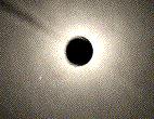
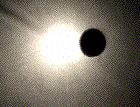
In order to simulate the formation of lensed images by a given mass distribution (point mass, etc.), we have used the optical setup that is shown in Fig. 1.
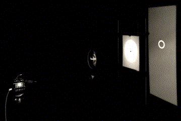
A compact light source is located on the left side (not clearly seen), then comes the point mass optical lens (cf. Fig. 3, in section 3, left) that deflects the light rays very nearly as a black hole having one third of the Earth mass. Behind the lens, we find a white screen with a small hole at the center (pinhole lens). Further behind, there is a large screen on which is projected the lensed image(s) of the source (the Einstein ring, in this case) as it would be seen if our eye were located at the position of the pinhole. In the example illustrated here, the pinhole is set very precisely on the optical axis of the gravitational lens so that the source, the lens and the pinhole (observer) are perfectly aligned. Some smoke in this experiment reveals the existence of a bright `pseudo- focal' line along the optical axis. Intersection of this line with the pinhole screen thus consists of a bright white spot (cf. Figure 2a). Note that the bright regions seen on the lens in Fig. 1 are essentially caused by scattered light. Let us now produce a second type of gravitational lens mirage: as we move the pinhole very slightly away from the symmetry axis (Fig. 2b), the Einstein ring breaks in two images which angular separation remains comparable with the diameter of the Einstein ring (Fig. 2c).
 |  |  |
The effects of a typical non symmetric (singular) gravitational lens may be simulated by simply tilting the optical lens around its vertical axis. In this case (see Fig. 3a), the bright (focal) line along the optical axis which existed in the symmetric configuration (cf. Fig. 2a) has changed into a two dimensional caustic surface, a section of which is seen as a diamond shaped caustic (made of four folds and four cusps) in the pinhole plane. As a result, the Einstein ring that was observed in the symmetric case has now split up into four lensed images (Fig. 3b). Such a configuration of four lensed images always arises when the pinhole (observer) lies inside the diamond formed by the caustic. Let us immediately note that such caustics constitute a generic property of gravitational lensing, the focal line in the symmetric configuration being just a degenerate case. Fig. 3d shows the merging of two of the four images into one, single, bright image when the pinhole approaches one of the fold caustics (Fig. 3c). Just after the pinhole has passed the fold caustic (see Fig. 3e), the two merging images have totally disappeared (Fig. 3f).

A particularly interesting case occurs when the pinhole (observer) is located very close to one of the cusps (cf. Fig. 3g). Three of the four previous images have then merged into one luminous arc, whereas the fourth one appears as a faint counterimage (Fig. 3h). For large sources that cover most of the diamond shaped caustic (Fig. 3i), an almost complete Einstein ring is observed (Fig. 3j), although the source, lens and observer are not perfectly aligned and the lens is still being tilted. In this last experiment, the increase of the source size has been simulated by enlarging the pinhole radius by a factor 4. In order to show that this is a correct simulation, one may consider the pinhole and the screen behind it as a camera. It is then clear that an increase in the size of the pinhole leads to a larger and less well focused image of the compact source, corresponding indeed to an increase in the source size. A more detailed and rigorous analysis does confirm this result.
In Table1, we are presenting known gravitational lens systems which display image configurations similar to the generic ones simulated in the gravitational lens experiment.
This optical gravitational lens experiment may also be used to simulate the formation of multiple giant luminous arcs and arclets seen near massive foreground galaxy clusters. In order to do so, we may simply replace the single pinhole screen by a cardboard perforated with multiple pinholes. In the absence of light deflection (i.e. by simply removing the optical lens), direct (non distorted) images of the circular background galaxies would be seen by an observer, alike those projected on the distant white screen (Fig. 4, left).
When inserting the optical lens between the light source and the multiple pinholes screen, images of the background galaxies get distorted (arclets) and/or transformed into multiple images, including giant luminous arcs (see Figs. 4 middle and right as possible examples). While covering the pinholes with various transparent colored filters, the distorted background galaxies look very much like those observed with the Hubble Space Telescope around the foreground galaxy cluster Abell 2218 (see HST press release). More generally speaking, the image configurations illustrated in Figs. 3a-j and 2b-c are all found among the observed gravitational lens systems accessible on one of our web pages (click here). It is of course obvious that if our optical lens would have been constructed non-singular in the center (cf. the 'spiral galaxy' optical lens shown in Fig. 3, section 3, right), we would have seen an additional image formed in the central part of the lens. For most of the known lenses with an even number of observed images, it may well be that a black hole resides in the center of the lens. The presence of a compact core could also account for the "missing" image since then the very faint image expected to be seen close to, or through the core, would be well below the detection limits that are presently achievable.
5.1 Gravitational lensing and the wine glass experiment
The formation of multiple images of a distant quasar by the gravitational
lensing effects of a foreground galaxy may be very simply, and faithfully, accounted for by the wine glass experiment described below.
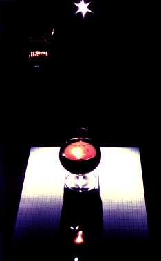 Figure 1:
The wine glass experiment. A bright compact light source
is used as a distant quasar. The wine glass set on the
table (cf Figure 2) distorts the light rays from the quasar and
produces a caustics having a triangular shape (see the enlargment in Figure
3). In order to see the multiple images from the distant quasar, put the
glass at the very edge of the table and one of your eyes around the caustics
(see text)
Figure 1:
The wine glass experiment. A bright compact light source
is used as a distant quasar. The wine glass set on the
table (cf Figure 2) distorts the light rays from the quasar and
produces a caustics having a triangular shape (see the enlargment in Figure
3). In order to see the multiple images from the distant quasar, put the
glass at the very edge of the table and one of your eyes around the caustics
(see text)
In order to successfully make this experiment, please use as the quasar light source a candle, or a bright compact light source as shown in Figure 1. This light source is set at a typical distance of several meters, and somewhat higher, from a table on which a glass full of wine is placed. Like a gravitational lens, the wine glass distorts the background field. This space distortion is very well seen through the glass in Figure 2. Because of the presence of the wine glass, the distribution of light on the table is no longer uniform (see Figure 1). Just behind the glass, higher concentrations of light may be seen at some locations in the form of a caustics (i.e. the intersection of a three-dimensional caustics with the plane of the table). The latter is, in the present case, approximately triangular. The three sides and summits of this triangular caustics are named folds and cusps, respectively.
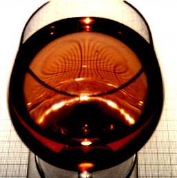 Figure 2: When looking through the wine glass, the distortion of the background field (millimetric paper) by the lens is very conspicuous
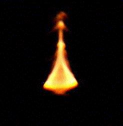
A blow up of this caustics is shown in Figure 3. The folds result from the envelope of pairs of tangent light rays from the candle. As a result, an
observer setting his eye on a fold will see a pair of merging images from the
distant quasar. Three merging images will be seen at the location of a cusp.
In order to be able to put your eye at various locations with respect to the
caustics, it is recommended to put the glass at the very edge of the table.
You may then also observe that the total number of images increases by two
when your eye crosses a fold from outside to inside the caustics. Figure 4
shows a photograph made with a camera set up at the center of the caustics. Up
to 9 different images of the compact light source are visible. As an exercise,
draw the various diagrams showing the multiple image configurations of the
background light source for different positions of your eye with respect to
the caustics (folds and cusps) and compare them with the multiple image
configurations observed for the known cases of multiply imaged quasars (a
gallery of pictures illustrating various cases of multiply imaged quasars is
available via the URL:
https://vela.astro.uliege.be/grav_lens/.
Note that the formation of caustics of light is a very generic feature in
nature. It arises whenever a foreground object (cf. the wine glass in the
above experiment, a galaxy acting as a gravitational lens, the wavy interface
between air and water in a swimming pool, on a lake, etc.) distorts the
propagation of light rays from a distant light source. For instance, for each
pair -among the billions- of quasars and galaxies that exist in the Universe,
a more or less complex three dimensional caustics is formed behind each
galaxy. Whenever an observer lies close to such a caustics, the former sees
multiple images of the distant quasar. Due to the relative motion between the
quasar, the lensing galaxy and the observer, this phenomenon does not last for
ever. It can be shown that the typical lifetime of a cosmic mirage involving a quasar and a
lensing galaxy is of the order of 20 million years.
 |
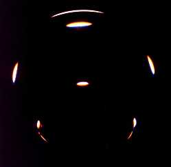 |
| Figure 3:Enlargment of the triangular caustics visible in Figure 1. The caustics results from the redistribution of light rays emitted from the quasar by the wine glass | Figure 4:Multiple images of the compact light source seen by the objective of a photographic camera placed near the center of the caustics |
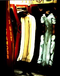
5.2 Multiple imaging as seen by whales and sharks
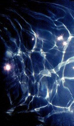
As already stated in the previous section, because of the wind, the interface
between the air and the water in a swimming pool, on a lake, on a sea, etc.,
is wavy and as a result, the propagation of light rays from a
distant source (cf. the sun, the moon, etc.) gets distorted after entering
water. Here also, complex caustics are formed and Figure 5a reproduces a view
of such caustics projected on the body of a swimmer in a pool. Figure 5b
illustrates also very well the caustics projected on the body of a whale, as
drawn by the famous american painter Miller. There is consequently no doubt
that, whenever one of the eyes of a whale crosses the folds (resp. the cups)
of the complex caustics, the sun, the moon ... appear to them in the form of,
continuously moving and changing, multiple images. Such multiple images, seen
by real sharks inside the large pool at Sea World (Orlando), have been
photographed and are reproduced in Figures 6a and 6b.
 |  |
 |  |
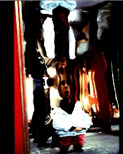
5.3 Multiple imaging at the House of Mirrors
Finally, it is fun to observe multiple images of human beings at the House of Mirrors, available during most of the big city fairs. Such mirages are produced by curved mirrors which distort light rays emitted from the surroundings. Several photographs taken during the Liège october fair in 1989 are reproduced in Figures 6a and 6b.
 |  |
Surdej, J.: 1990, review paper, Lecture Notes in Physics, Gravitational Lensing, eds Y. Mellier et al., Vol.360, p.57, "Observational aspects of gravitational lensing"
Refsdal, S., Surdej, J.: 1992, First invited discourse, XXIst IAU General Assembly, Highlights in Astronomy, ed. J.Bergeron, Vol.9, p.3, "Gravitational Lensing"
Refsdal, S., Surdej, J.: 1994, Reports Progress in Physics, Vol.57, 117, "Gravitational Lenses"
Surdej, J., Refsdal, S., Pospieszalska-Surdej, A., 1993, 31st Liège International Astrophysical Colloquim, Gravitational Lenses in the Universe, eds J.Surdej et al., p.199, "The optical gravitational lens experiment"
Surdej, J., Refsdal, S., Pospieszalska-Surdej, A., 1995, IAU, Symposium No.173, Astrophysical Applications of Gravitational Lensing, eds C.S. Kochanek and J.N. Hewitt, p.417, "Formation of giant luminous arcs and arclets using an optical gravitational lens experiment"