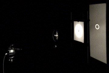
In order to simulate the formation of lensed images by a given mass distribution (point mass, etc.), we have used the optical setup that is shown in Fig. 1.
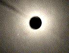
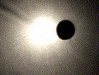
A compact light source is located on the left side (not clearly seen), then comes the point mass optical lens (cf. Fig. 3, in section 3, left) that deflects the light rays very nearly as a black hole having one third of the Earth mass. Behind the lens, we find a white screen with a small hole at the center (pinhole lens). Further behind, there is a large screen on which is projected the lensed image(s) of the source (the Einstein ring, in this case) as it would be seen if our eye were located at the position of the pinhole. In the example illustrated here, the pinhole is set very precisely on the optical axis of the gravitational lens so that the source, the lens and the pinhole (observer) are perfectly aligned. Some smoke in this experiment reveals the existence of a bright `pseudo- focal' line along the optical axis. Intersection of this line with the pinhole screen thus consists of a bright white spot (cf. Figure 2a). Note that the bright regions seen on the lens in Fig. 1 are essentially caused by scattered light. Let us now produce a second type of gravitational lens mirage: as we move the pinhole very slightly away from the symmetry axis (Fig. 2b), the Einstein ring breaks in two images which angular separation remains comparable with the diameter of the Einstein ring (Fig. 2c).
 |  |  |
The effects of a typical non symmetric (singular) gravitational lens may be simulated by simply tilting the optical lens around its vertical axis. In this case (see Fig. 3a), the bright (focal) line along the optical axis which existed in the symmetric configuration (cf. Fig. 2a) has changed into a two dimensional caustic surface, a section of which is seen as a diamond shaped caustic (made of four folds and four cusps) in the pinhole plane. As a result, the Einstein ring that was observed in the symmetric case has now split up into four lensed images (Fig. 3b). Such a configuration of four lensed images always arises when the pinhole (observer) lies inside the diamond formed by the caustic. Let us immediately note that such caustics constitute a generic property of gravitational lensing, the focal line in the symmetric configuration being just a degenerate case. Fig. 3d shows the merging of two of the four images into one, single, bright image when the pinhole approaches one of the fold caustics (Fig. 3c). Just after the pinhole has passed the fold caustic (see Fig. 3e), the two merging images have totally disappeared (Fig. 3f).

A particularly interesting case occurs when the pinhole (observer) is located very close to one of the cusps (cf. Fig. 3g). Three of the four previous images have then merged into one luminous arc, whereas the fourth one appears as a faint counterimage (Fig. 3h). For large sources that cover most of the diamond shaped caustic (Fig. 3i), an almost complete Einstein ring is observed (Fig. 3j), although the source, lens and observer are not perfectly aligned and the lens is still being tilted. In this last experiment, the increase of the source size has been simulated by enlarging the pinhole radius by a factor 4. In order to show that this is a correct simulation, one may consider the pinhole and the screen behind it as a camera. It is then clear that an increase in the size of the pinhole leads to a larger and less well focused image of the compact source, corresponding indeed to an increase in the source size. A more detailed and rigorous analysis does confirm this result.
This optical gravitational lens experiment may also be used to simulate the formation of multiple giant luminous arcs and arclets seen near massive foreground galaxy clusters. In order to do so, we may simply replace the single pinhole screen by a cardboard perforated with multiple pinholes. In the absence of light deflection (i.e. by simply removing the optical lens), direct (non distorted) images of the circular background galaxies would be seen by an observer, alike those projected on the distant white screen (Fig. 4, left).

When inserting the optical lens between the light source and the multiple pinholes screen, images of the background galaxies get distorted (arclets) and/or transformed into multiple images, including giant luminous arcs (see Figs. 4 middle and right as possible examples). While covering the pinholes with various transparent colored filters, the distorted background galaxies look very much like those observed with the Hubble Space Telescope around the foreground galaxy cluster Abell 2218 (see HST press release). More generally speaking, the image configurations illustrated in Figs. 3a-j and 2b-c are all found among the observed gravitational lens systems accessible on one of our web pages (click here). It is of course obvious that if our optical lens would have been constructed non-singular in the center (cf. the 'spiral galaxy' optical lens shown in Fig. 3, section 3, right), we would have seen an additional image formed in the central part of the lens. For most of the known lenses with an even number of observed images, it may well be that a black hole resides in the center of the lens. The presence of a compact core could also account for the "missing" image since then the very faint image expected to be seen close to, or through the core, would be well below the detection limits that are presently achievable.